Hi Pierre,
You can not connect step/dir to the Kanalog Board.
If you need Step/Dir with Kanalog unplug the RJ45 cable (JP5 from KFLOP) and use those 4 Step/Dir outputs. You will loose differential encoder inputs 8-15 on Kanalog, but the remainder of Kanalog will still work.
Regards
TK
| Group: DynoMotion |
Message: 342 |
From: Peter Tannoury |
Date: 5/2/2010 |
| Subject: Re: kanalog and stepper motor |
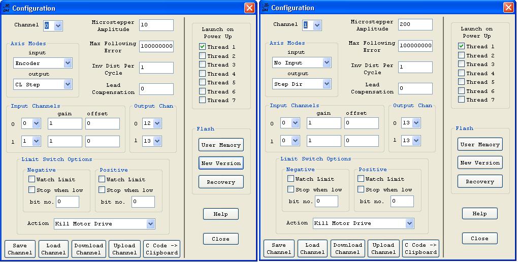
Dear Tom, it's confusing a little bit what's happening, i spent 2 days with this small problem, i did spent 2 days of testing to be able to understand exactly what's happening to be able to send you a figure the application consist of control stepper motors drives connected to KFLOP and Kanalog, you told me that i should use the RJ45 JP5 of KFLOP and i will lose the 8 to 15 encoders, i connect the stepper drive to RJ45 JP5 (pulse- to pin 1, Dir to pin 2 and pulse+ and Dir+ to VCC5V on Kanalog) i install the kmotion software 4.19 and i update the firmware of KFLOP, i tried to configure channels without encoders, so for axe 0 i used output channels 12 and 13 (12 and 13 are the only working bits in response testing and make the stepper move ( i used my digital oscilloscope to
found that) attached picture show's you the configuration i made, for axe 0 i used channel 0 and channel 1 but i can't configure axe 2 because i tried all combination of output channels and none work, just 12 and 13 connected to pin 1 and 2, the second stepper drive is connected to JP5 pin 3(pul-) and pin4(Dir-) can you explain how can i configure both axes with clear procedure, i tried to follow the Help (section RJ45 JP5 signal and bits) it's totally different then real, please advice, all what i want is to connect 2 Stepper drives to KFLOP+KANALOG or KFLOP alone, I tried also to connect the axe 0 directly to JP7 after removing the 26pin Riban cable, and i tried all bits combination, for axe 0 the working channel for CL step was bit 8 and Step Dir to bit 9 ( i connect PULSE- to pin15 and Dir to pin 16 of JP7 and also VCC5V to 23) this is working but i figure out that bits numbers are different then user manual connector pinouts
bits Please advice by the way, as an advice if possible, you should add to your page application examples including schematics, configuration and tuning, this way we can take the example and change what necessary especially that in motion 75 % of the design is same Thanks in advance Pierre
| Group: DynoMotion |
Message: 343 |
From: Tom Kerekes |
Date: 5/2/2010 |
| Subject: Re: kanalog and stepper motor [1 Attachment] |
Hi Peter
Sorry about your confusion/frustration.
All you should need to do is:
#1 Load our SimpleStepDirAxis0.mot example into an axis channel.
#2 Change the OutputChan0 to the Step/Dir Generator you want to use.
#3 Wire Pulse- and Dir- to the Step/Dir Generator KFlop Output pins.
#4 Wire Pulse+ and Dir+ to +5V
#5 Push "Move" on the Step Response Screen.
I think possibly the confusion is that you are thinking that the Configuration Output Settings are defining I/O bit numbers or Pin numbers to use in a way similar that Mach3 uses to define output pins. They do not and that might be why you think the documentation is incorrect. Only one of the two output settings is actually used for Step/Dir Output modes. OutputChan0 is used. OutputChan1 is not used at all. The value of OutputChan0 should be set to which Step Dir Generator you wish to use. Maybe this will help:
Another possible point of confusion is that you cannot look at an open collector output with an oscilloscope without something else connected to provide a source. Such as the drive or a pullup resistor. This is because whether the pin is being driven to ground or open circuit the pin will remain at 0V and you will see nothing on the scope.
However adding 8 to the OutputChan0 number switches the Step Dir Generator from open collector mode to LVTTL mode which is why you then see something on your scope. See:
In your case you will want to use Step/Dir Generators 4 and 5 for your two drives connected to JP5 if (like most drives) they are best driven in open collector mode.
Also:
Why are you trying "CL Step" mode? Please get "Step Dir" mode to work first.
Why are you Launching a User Program on start up? What does the program do? We don't recommend this unless you need to run stand alone.
I hope this helps.
Regards
TK
| Group: DynoMotion |
Message: 348 |
From: Peter Tannoury |
Date: 5/4/2010 |
| Subject: Re: kanalog and stepper motor |
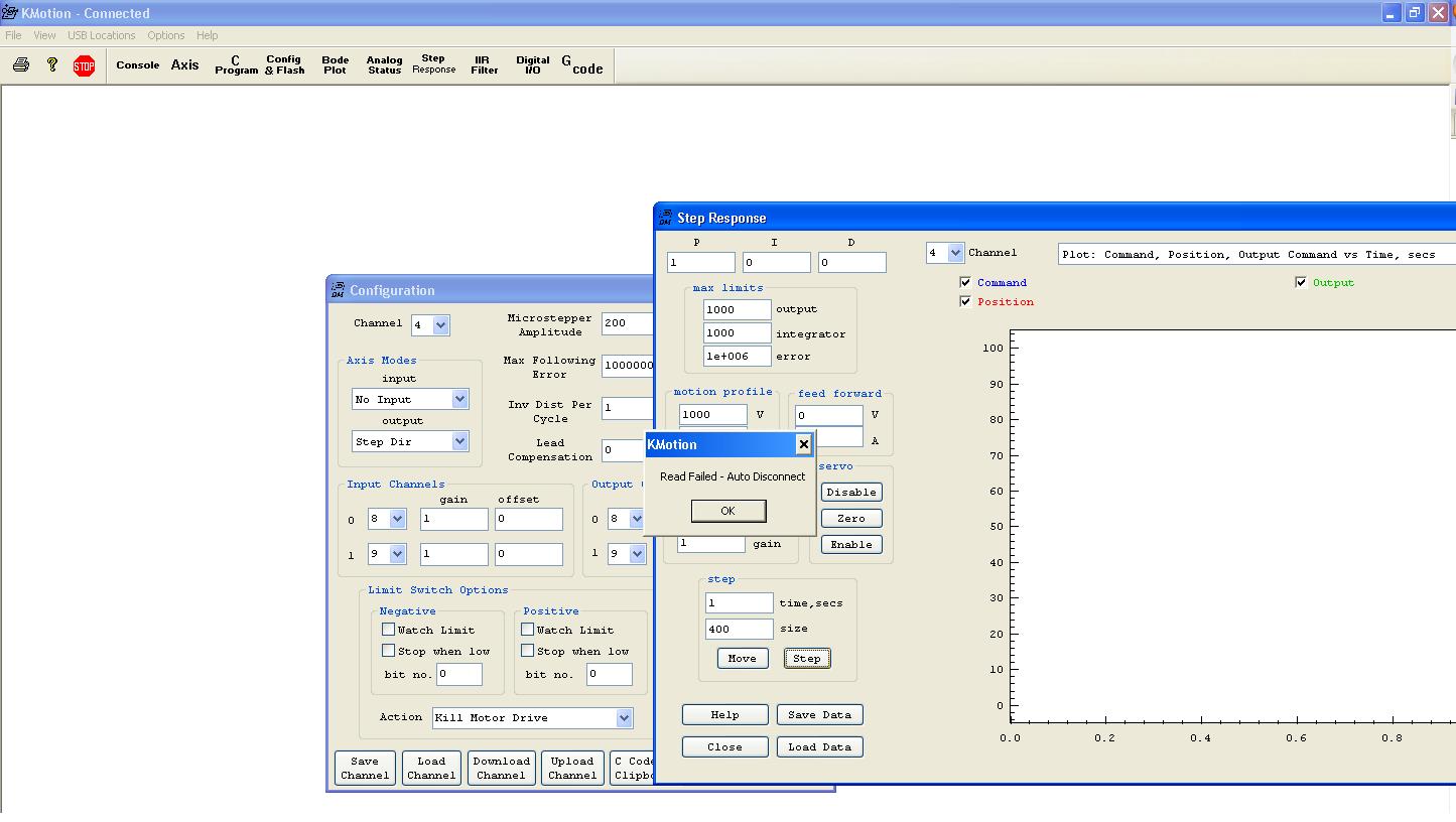
Thank you Dear Tom for the useful information you sent, i did what you ask me to do but I'm receiving an error message when press step or move see attached picture i used JP5 pin1 and 2 and i tried ch0 then i tried ch4 with 8 and 9 outputs waiting your advice Thanks in advance
| Group: DynoMotion |
Message: 349 |
From: Tom Kerekes |
Date: 5/4/2010 |
| Subject: Re: kanalog and stepper motor [1 Attachment] |
Hi Peter,
JP5 pins 1 and 2 are connected to Step Dir Generator #4. Why did you use 8 and 9? Only the first number (OutputChan0) is used. It doesn't matter what the second number is. Try OutputChan0=4.
But OutputChan0 set to 8 instead of 4 should not cause KFlop to Disconnect. There must be something else wrong. Look at the Console screen to see if there is an error printed. There are 3 screens related to an axis's setup :Config/Flash, Step Response, and Filter. Please send screen shots of those 3 screens. What versions are you running (type Version on the console screen, then look at Help|About in KMotion.exe).
What are your Windows Regional Settings set at? Try English if that isn't what you have set.
Sorry for the frustration. If you want me to call you and/or connect to your machine email me off-line and we can arrange a time.
Thanks
TK
| Group: DynoMotion |
Message: 350 |
From: Peter Tannoury |
Date: 5/4/2010 |
| Subject: Re: kanalog and stepper motor |
Dear Tom,
i will try using another PC but windows 7 instead of XP SP3.
i will keep you posted
I'm using version 4.19 and i load the last firmware coming with the kmotion 4.19 software
now i will remove kanalog JP7 and already i removed J5and i want to try connect axe 0 and 1, so this way i can use simple examples comming with kmotion simplestepdiraxis0.mot and axis1.mot, i will let you know what's happening.
the drivers of steppers are optically isolated they are very simple, now for axe 0: PULS- connected to JP7-PIN15 and Dir- connected to JP7-PIN16
for axe1: PULS- connected to JP7-PIN17 and Dir- connected to JP7-PIN18 and common VCC connected to JP7-PIN23
i will make testing on another machine and i will back to you soon.
Thanks
Peter
| Group: DynoMotion |
Message: 351 |
From: Peter Tannoury |
Date: 5/4/2010 |
| Subject: Re: kanalog and stepper motor |
Dear Tom, here attached motors files of my 2 axes and it's working using another PC with KFLOP only now, please check these files and give your feedback about if it's logical or not? thanks in advance
| Group: DynoMotion |
Message: 352 |
From: Tom Kerekes |
Date: 5/4/2010 |
| Subject: Re: kanalog and stepper motor [4 Attachments] |
Why did you send 4 files?
TK
| Group: DynoMotion |
Message: 353 |
From: Peter Tannoury |
Date: 5/4/2010 |
| Subject: Re: kanalog and stepper motor |
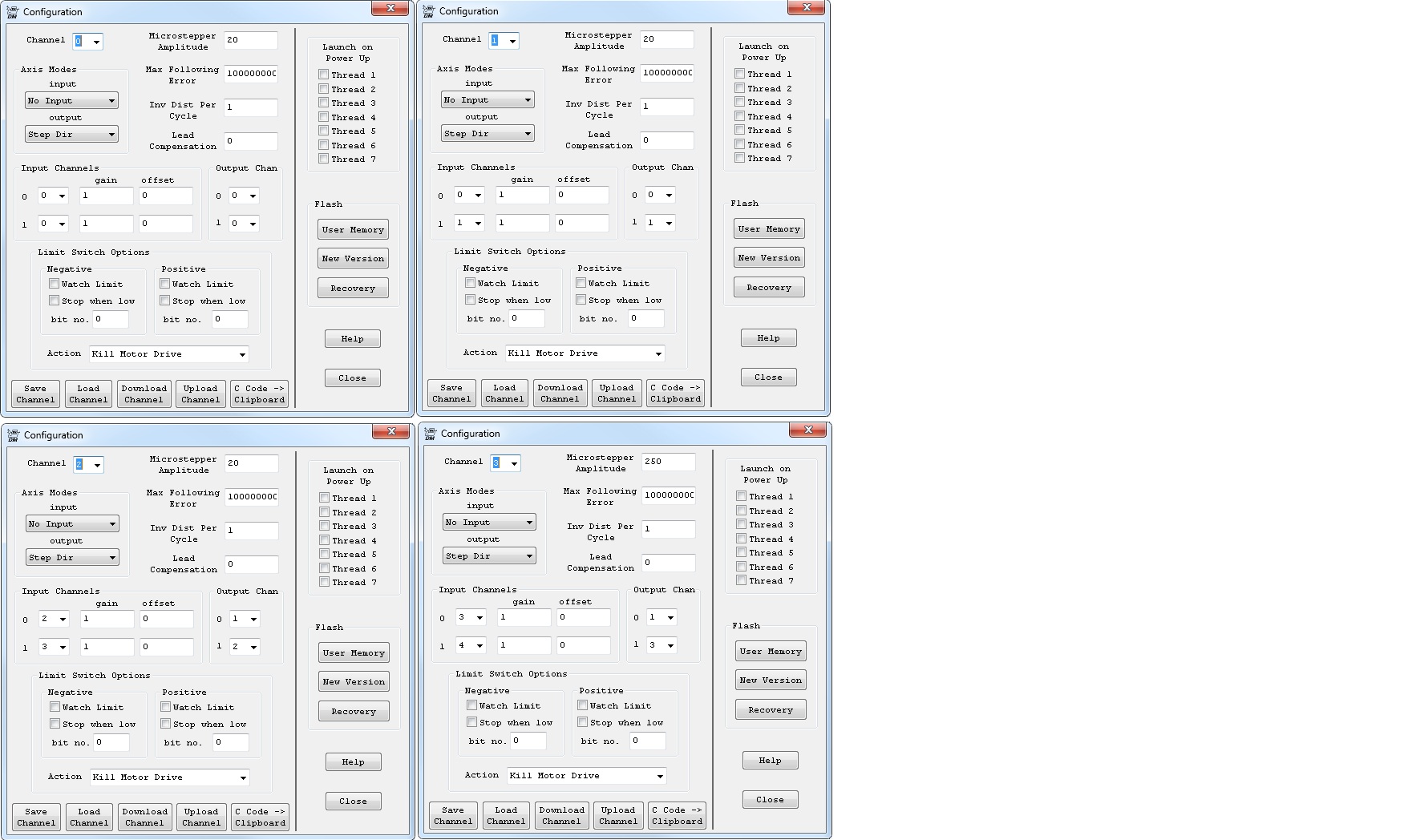
Dear Tom, here my new results you asked why i sent you 4 motors files, plz check attachment picture, this showing that i can't configure ch0 and ch1 as it suppose to be,i already load the simple axe0 and axe1 from your examples but nothing work, because nothing turn if i do the standard procedure pictures show's you that i can move axe 0 from ch0 and ch1, and i can move axe 1 using ch2 and ch3, can you tell me what's wrong with me? how can i define ch0 for axe0 and ch1 for axe1? you can make remote access to my PC by entering the following IP:213.204.117.91, user name:administrator, password:911 I'm waiting your reply thanks To: DynoMotion@yahoogroups.com
Sent: Tue, May 4, 2010 8:28:27 PM
Subject: Re: [DynoMotion] kanalog and stepper motor
Why did you send 4 files?
TK
| Group: DynoMotion |
Message: 354 |
From: Peter Tannoury |
Date: 5/5/2010 |
| Subject: Re: kanalog and stepper motor |
Dear Tom, here my new results you asked why i sent you 4 motors files, plz check attachment picture, this showing that i can't configure ch0 and ch1 as i suppose to be, because nothing turn if i do the standard procedure pictures show's you that i can move axe 0 from ch0 and ch1, and i can move axe 1 using ch2 and ch3, can you tell me what's wrong with me?
| Group: DynoMotion |
Message: 355 |
From: Tom Kerekes |
Date: 5/5/2010 |
| Subject: Re: kanalog and stepper motor [1 Attachment] |
Peter,
Please answer each of the following questions because I think we are mis-communicating on some fundamental things that we need to get straight:
#1 - Do you understand that you have both Axis Channel 0 and Axis Channel 1 set to the SAME Step and direction Generator #0 (OutputChan0=0)?
#2 - Do you understand that you have both Axis Channel 2 and Axis Channel 3 set to the SAME Step and direction Generator #1 (OutputChan0=1)?
#3 - Do you understand the difference between OutputChan0 and OutputChan1?
#4 - Do you understand that OutputChan1 is NOT USED when using Step/Direction Drives?
#5 - Have you tried using only 2 Axis channels to drive your 2 motors?
#6 - If you have tried 2 Axis channels to drive the 2 motors, please send screen shots of the two configurations screens showing that the first has OutputChan0=0 and the second has OutputChan0=1.
We realize this is very confusing and are looking at ways to make it simpler to configure. It must be extra difficult if English isn't your first language.
Thanks
TK
| Group: DynoMotion |
Message: 356 |
From: Peter Tannoury |
Date: 5/5/2010 |
| Subject: Re: kanalog and stepper motor |
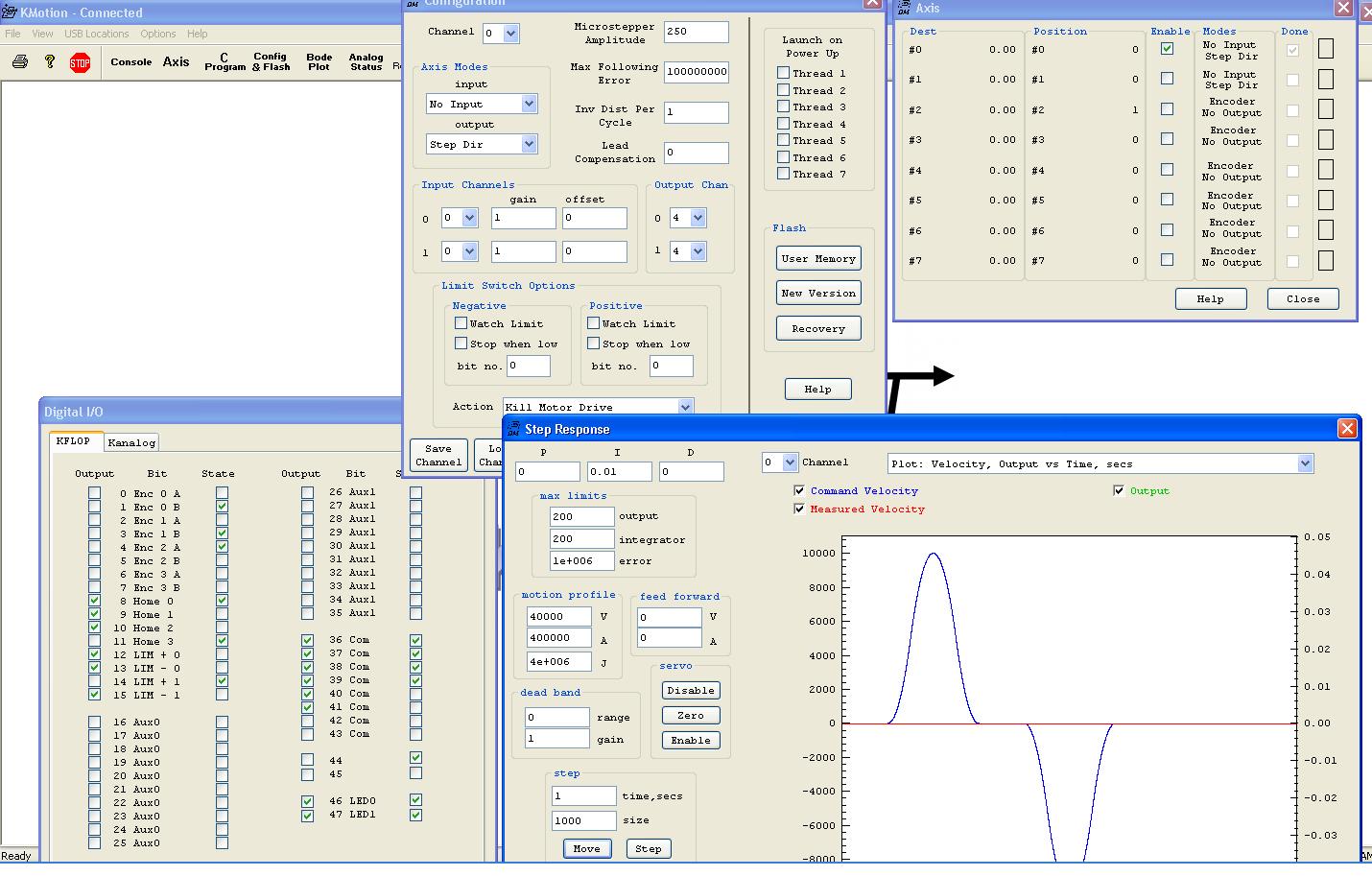
Tom, this exactly what's confusing me, i understand all what you are trying to explain to me, I'm not a beginner in this field, and I made a data acquisition card in 1999. so this problem is not normal and tomorrow i will bring the other KFLOP card and testing the simple standard procedure. but i told you and i will say again this is how motors turn, i sent you this picture of diagnostics to help you understand what's happening exactly inside the KFLOP controller, i understand that current axes configuration(shown in pictures) is not logical i will make a simple procedure again from beginning: this simple test for one axe only to show you that even one axe is not working in a regular way Hardware Installation: 1. A stepper motor connected to a leadshine
stepper driver model DM556 (already tested using manufacturer application). 2. Stepper controller "pulse-" connected to kflop JP5 pin1, direction- connected to JP5 pin2, pulse+ and direction+ connected to Kanalog +5V (Kanalog connected to KFLOP via JP7) Software 1. I connect the KFLOP to the USB and i install Kmotion software version 4.19 and USB driver 2. Run the kmotion software and upgrade the firmware to 4.19 3. Reboot KFLOP then from console press send "Version", Return: KFLOP 4.19 Build 15:47:33 Dec 11 2009, KFLOP 4.19 Ready 4. From Config & Flash press "Load Channel" button for Channel 0 (axe0) 5. Select "Simple StepDirAxis0.mot 6. Change Axes Modes Input to "No Encoder" 7. Change Both Output Chan to 4 8. Inputs Channels=0 9. I Press Download Channel to send data to KFLOP 10. From Step Response i pressed Step then Move Result: nothing move attached picture show's
you the configuration i hope with my second English language be able to send you a good figure
Thanks in advance
Peter
| Group: DynoMotion |
Message: 357 |
From: Tom Kerekes |
Date: 5/5/2010 |
| Subject: Re: kanalog and stepper motor [1 Attachment] |
Hi Peter,
After our phone conversation, I looked up the drive specs. See:
Going along with our suspicion that the issue may be a hardware issue with KFLOP driving the proper step pulses I see that the drive requires:
#1 minimum of 2.5us pulses - KFLOP defaults to 2us. Change to 4us using C code of:
FPGA(STEP_PULSE_LENGTH_ADD) = 63;
#2 less than 0.5V to turn off - KFLOP open collector will clamp at ~+4V (1V relative to +5V)
#3 More than 4V to turn on - KFLOP is probably OK there
#4 a max of 16ma to turn on - KFLOP specs only 12ma
#5 Direction must change 5us before step - KFLOP doesn't meet this.
The most important issues are probably #1 and #2.
Let us know what you find
Thanks
TK
| | | | | | | | | | | | | | | | | | | | | | | | | |